
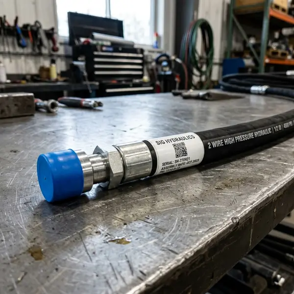
Hydraulic hose fitting identification is not a matter of finding two threads that seem to screw together. A dependable identification uses several clues together: where the connection seals, whether the thread is straight or tapered, the thread pitch, the measured diameter, the seat shape, and any manufacturer or port markings. JIC, ORFS, NPT, BSPP, and metric fittings can overlap in apparent size while relying on very different sealing surfaces.
This guide gives equipment owners a practical way to collect useful information without pretending that a photograph can replace a trained, hands-on inspection. It supports SIG Hydraulics’ custom hose fabrication service by helping customers document the machine and connections before requesting service.
Safety before identification
Do not loosen, rotate, touch, or measure a connection while a hydraulic system may contain pressure. A shut-off engine does not prove that stored energy is gone. Raised attachments, accumulators, cylinders, and trapped sections of a circuit can retain hazardous energy.
The OSHA control-of-hazardous-energy overview identifies hydraulic energy as a source that must be controlled during servicing. OSHA’s typical lockout procedure also explains that stored or residual energy must be dissipated or restrained. Follow the equipment manufacturer’s shutdown and pressure-relief procedure and your employer’s energy-control program. If you are not authorized and trained to isolate the machine, stop at photographs, labels, and documentation that can be collected safely.
Never use a hand to search for a pinhole leak. Escaping fluid can penetrate skin. The Gates hydraulic hose catalog includes manufacturer safety guidance for hose selection, assembly, installation, inspection, and leaks. A suspected injection injury needs immediate emergency medical evaluation, even when the initial wound appears small.
For a broader visual inspection before a failure, use our guide to the warning signs of hydraulic hose damage. If a hose has already failed, review the equipment shutdown and spill-control guide without treating it as a substitute for the machine manual.
The five families at a glance
| Fitting family | Most useful first clue | Typical sealing principle | Identification trap |
|---|---|---|---|
| JIC | Conical metal seat | Metal flare contacts matching seat | Confused with other flared fittings |
| ORFS | Flat face with visible O-ring groove | O-ring compressed between flat faces | Thread may look similar to another straight thread |
| NPT or NPTF | Tapered pipe thread | Thread interference, with the specified sealing method | Confused with BSP tapered or treated as a reusable swivel joint |
| BSPP | Straight, parallel thread | Separate cone, bonded seal, O-ring, or defined port face | Thread alone does not identify the sealing style |
| Metric | Metric pitch and diameter | Varies by connector system | “Metric” describes the thread system, not one universal seal |
That table is a screening tool, not a parts-ordering chart. The exact connector standard, material, hose series, pressure capability, temperature range, fluid compatibility, and manufacturer-approved assembly system still have to match the application.
A repeatable fitting-identification process
When a connection can be inspected safely, work in this order.
1. Start with documentation
Record the machine manufacturer, complete model, serial or product identification number, attachment, and the function served by the hose. Look for a legible part number on the original hose, fitting, port, parts diagram, or service manual. A manufacturer part number is usually stronger evidence than a visual guess.
Photograph the entire hose routing before anything is moved. Include both ends, nearby adapters, clamps, guarding, and the component each end enters. The wide view helps distinguish the hose end from an adapter that remains on the machine.
2. Find the actual sealing surface
Ask, “What surfaces stop the fluid?” The threads may only provide clamping force.
- A conical metal seat points toward a flare-type connection such as JIC, but the seat angle and mating system still need confirmation.
- A flat face with an O-ring groove strongly suggests ORFS.
- A tapered pipe thread may seal through controlled thread interference and the method specified for that connection.
- A straight BSPP or metric stud may use an O-ring, bonded washer, cutting ring, cone, or another defined sealing interface.
Do not add an O-ring or sealant simply because a connection leaked. Using a sealing method that was not designed for the port can hide a mismatch, contaminate the system, or prevent correct engagement.
3. Determine whether the thread is straight or tapered
On an exposed male thread, a tapered thread becomes gradually wider toward the hex; a parallel thread maintains substantially the same outside diameter. The difference can be subtle over a short thread length, so visual inspection alone is not enough. A second diameter measurement at a different point can help a trained person confirm taper.
4. Measure diameter and pitch
Use clean calipers and the correct thread-pitch gauge. Measure a male thread across its outside crests. A female thread requires a different measurement and reference chart. Record the measurement rather than rounding it to the nearest familiar fractional size.
Thread pitch may be recorded as threads per inch or as the distance between metric thread crests. These systems are not interchangeable. If a gauge does not fit cleanly across several threads, do not force the answer.
5. Confirm seat geometry and seal condition
Use a seat-angle gauge where applicable; do not estimate the angle by eye. Inspect an ORFS O-ring and groove for damage, but do not pick at the seal while the connection is installed. Record whether a straight-thread port uses an O-ring, bonded seal, cone, shoulder, or another feature.
6. Cross-check a current manufacturer catalog
Compare all observations with the machine documentation and the intended hose-and-fitting system. Danfoss publishes an official rubber hydraulic hose and fitting catalog that demonstrates how manufacturers distinguish fitting families, hose compatibility, and part-number conventions. Parker’s official hydraulic hose and fitting catalog likewise treats the end connection as one part of a complete manufacturer-specified assembly.
Do not mix a hose, stem, and ferrule because the pieces appear to fit. The finished assembly must use a validated combination and the manufacturer’s crimp specification.
How to recognize JIC fittings
JIC is the familiar name used for a 37-degree flared connection in ground-vehicle and industrial hydraulic applications. The male side presents an external conical nose. The female side contains the matching internal flare, and a straight UN/UNF thread draws the two seats together. The sealing action occurs at the metal seats—not on the thread.
SAE J514 covers 37-degree flared and other hydraulic tube-fitting requirements. The important field lesson is that seeing a flare is not enough. SAE 45-degree flare fittings and some other connector families can look similar at a glance. A seat-angle gauge, thread measurement, and equipment documentation should agree before the fitting is named.
Common JIC clues include:
- a visible conical seat rather than a flat O-ring face;
- a straight thread behind the seat;
- no expectation that thread sealant creates the primary seal; and
- a matching metal flare on the mating half.
A scarred seat, distorted flare, wrong angle, contamination, or misalignment can leak even when the thread size appears correct. The correct response is not automatically “tighten it more.” Confirm the manufacturer’s installation method and inspect both mating surfaces.
How to recognize ORFS fittings
An O-Ring Face Seal connector is usually the easiest of these families to screen visually. The male end has a broad flat face with a machined groove that retains an O-ring. The female swivel has a flat mating face. Tightening the connection compresses the O-ring between those faces.
SAE J1453/1 addresses the material, dimensional, and performance requirements of ORFS connectors and the related hose-stem interface. In the field, verify all of the following:
- the face is flat rather than conical;
- the O-ring groove is in the expected location;
- the thread diameter and pitch match the connector specification;
- the O-ring material is compatible with the application; and
- the mating face is not scratched, dented, or contaminated.
Do not identify ORFS by thread size alone. The thread supplies clamping force while the O-ring performs the sealing. A missing or incorrect O-ring can turn a seemingly matched connector into a leak.
How to recognize NPT and NPTF connections
National Pipe Taper connections use tapered inch-based threads. As the mating threads engage, the fit becomes progressively tighter. Depending on the exact connection and manufacturer instructions, the sealing system may rely on the defined thread form and an approved sealant.
Useful NPT/NPTF clues include:
- visible taper confirmed by measurement;
- no separate flare or flat-face O-ring at the end;
- a pipe-thread callout in the machine manual or on the port; and
- engagement that changes as the tapered threads advance.
The major trap is assuming every tapered pipe fitting is NPT. BSPT is another tapered family, and its thread form and pitch conventions differ. A connection that begins to thread is not proof of compatibility. Do not use force to test a possible match, because partial engagement can damage both parts.
Pipe threads also should not be treated like a positioning swivel. Final orientation, engagement, and sealant use must follow the component manufacturer’s procedure.
How to recognize BSPP connections
British Standard Pipe Parallel uses straight threads commonly identified with a “G” designation. “Parallel” is the key word: the thread does not create a taper lock. BSPP describes the thread family, while the actual sealing arrangement depends on the connector and port design.
A BSPP connection may seal with a bonded washer under a shoulder, an O-ring at a port face, a cone seat, or another specified interface. Therefore, recording “straight pipe-looking thread” is incomplete. Photograph and document the end face, nose, shoulder, washer, O-ring, and mating port.
Do not confuse BSPP with NPT because the nominal pipe size sounds familiar. Do not confuse it with a metric thread because both appear parallel. The measured diameter, pitch, thread form, markings, and sealing surface have to tell one consistent story.
What “metric fitting” really means
Metric is not one fitting design. It means the thread diameter and pitch are expressed in millimeters, but several hydraulic connector systems use metric threads. A metric fitting may use a cone, an O-ring, a cutting ring, a flat face, or a defined port seal. Light and heavy tube-fitting series may also exist within a connector family.
For that reason, “M22” or “it looks metric” is not a complete identification. Capture:
- the measured major diameter;
- the measured pitch;
- whether the thread is parallel or tapered;
- the sealing surface and seat geometry;
- tube outside diameter, if a tube fitting is involved;
- manufacturer markings and the machine’s country or system origin; and
- the complete mating component, not only the loose hose end.
Metric and BSPP threads can be especially deceptive when a pitch is close. Never prove a fit with a wrench.
The most useful fitting photos
When collecting information for a mobile service request, take clear photos before the machine becomes an emergency. Our companion checklist explains what information to have ready for mobile hydraulic hose service.
For fitting identification, collect:
- one wide photo showing the hose route and machine component;
- one photo of each connection before removal;
- a straight-on view of the sealing face, only if it is already safely exposed;
- a side view showing the seat or nose profile;
- the thread beside a pitch gauge and caliper reading, when measured by a trained person;
- every stamped part number, hose layline, port code, or equipment label; and
- a ruler or known scale in the frame without covering the fitting.
Keep the images at full resolution. Add a simple label such as “pump end,” “boom end,” or “steering valve end.” A folder of unlabeled close-ups is harder to interpret than a smaller, organized set.
Identification errors to avoid
Ordering from hose outside diameter
Outside diameter varies by construction and manufacturer. It does not reliably establish the hose inside diameter, pressure class, or fitting series. Read the layline and cross-check the manufacturer data.
Reusing the old fitting as the only specification
An existing assembly may already be incorrect, obsolete, damaged, or built from mismatched components. Treat it as evidence, not unquestioned truth.
Assuming the machine brand determines every fitting
Attachments, replacement valves, adapters, imported components, and prior repairs can introduce several connector families on one machine. Identify the actual connection in front of you.
Measuring only one end
A hose can use different connector families, sizes, angles, or clocking at opposite ends. Document both ends and the full routing. Elbow orientation matters because twisting an assembly during installation can create stress.
Turning an informational match into a safety rating
Correctly naming the connector family does not establish the assembly’s working pressure, temperature range, fluid compatibility, impulse life, abrasion resistance, or bend requirements. Those are separate selections made from the hose and fitting manufacturer’s data for the application.
What this means for a SIG Hydraulics visit
SIG Hydraulics brings mobile fitting-identification and hose-fabrication capability to equipment across Northeast Ohio and nearby Western Pennsylvania. Explore the service area and mobile hydraulic hose repair service for more information.
Good documentation can shorten the identification stage. Save the machine details, fitting photos, hose layline, route, and component information in one maintenance record. You can also review the hydraulic hose FAQ and learn why SIG Hydraulics operates a mobile-only service.
To request service, tell SIG where your equipment operates. You can use the same form to ask a question about the mobile service.